E-Sharp News
June 2011
ANCA’s Cim3D was the world’s first high quality 3D tool simulation software system and it’s fair to say it revolutionised the industry. Version 7 of this industry benchmark package is now available with a range of new features to improve usability, enhance tool verification abilities, and better analyse the grinding process.
Cim3D is Now Faster
Version 7 is faster. Optimisation of the 3D calculation engine has resulted in more than a 30% average speed improvement in simulation time compared to V6. More dramatic performance enhancements can be achieved in some cases when using arc blank sections, which are now supported in version 7. Due to the reduction of material removed when using a pre-formed blank compared to a cylindrical blank, calculation time is reduced. For certain profile blanks, the time savings can be significant. This has two benefits. Not only can complex profile tools be simulated in less time, but also the detail of the simulation can be increased significantly compared to previous versions to provide a more accurate tool model for measurement and verification purposes. (The use of arc blank sections will be supported within the iGrind blank editor in Toolroom RN31.1-1 onwards.)
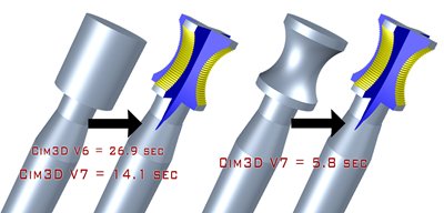
In the example pictured, the same tool simulated in 52% of the time in V7 compared to V6 in a high detail mode. When the actual radius blank was used, simulation time was reduced by almost 80%.
2D Overlays for Instant Visual Verification
The ability to verify geometrical features has been significantly extended in Cim3D V7 by providing the ability to import DXF overlays (2D CAD outline curves) into the measurement view. This can be used to verify various geometrical features of a tool such as the tool OD or core profile as well as the flute cross-section geometry. The DXF overlay can be conveniently enabled or disabled as required, as well as positioned and then locked with the tool model. The accuracy of the core and cutting profile display in Cim3D has also been improved in V7 so that DXF overlays can be accurately compared to these simulated profiles.
From October 2011, ANCA’s next release of the Toolroom software suite will provide the added benefit of automatically generating and sending the theoretical tool and cross section profiles to Cim3D, saving you even more time in the verification process. This will be particularly useful for ball-nose, corner radius, stepped and profile tools.
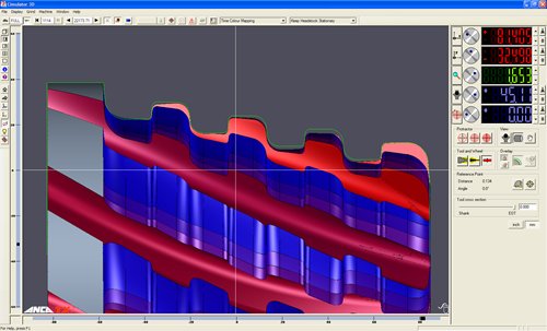
DXF overlays can be imported into the measurement view to verify tool geometry. In this example the theoretical cutting profile of a fir tree cutter (green) has been imported into the measurement view to compare against the simulated tool.
DXF overlays are also very useful to verify flute geometry. In this example the flute cross-section from iFlute has been imported into Cim3D (green) to verify that the correct flute shape has been achieved. Any deviation can be measured in the measurement view.
Quicker Set-up of Tooling and Accessory Models
Machine accessory configuration was potentially a cumbersome task in previous versions. The new machine configuration dialog simplifies the task of setting up machine accessories by providing one convenient interface to set-up standard machine tooling including tool-holding, support systems, and dresser configurations. Accurate 3D representation of the grinding process as well as the machine set-up allows processes to be optimised and aids in identifying potentially costly mechanical crashes.
A potential collision point on a grinding machine is the tool holding. Simulating the grinding process using an accurate model of the tool holder ensures that any potential collision is detected offline and is often easily rectified rather than causing a potentially costly collision. For this reason, DXF files can now also be imported into Cim3D to model tool holding. Tool holders can typically accommodate various collet or jaw sizes. To cater for this, a set of DXF files can be imported with various collet or jaw sizes to create a tool holding set. Cim3D can then automatically select the model based on shank diameter.
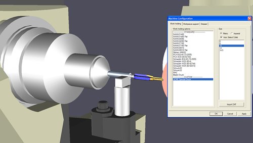
The new machine configuration dialog not only provides a convenient interface to set-up machine accessories, but also allows importing of DXF files to model special tool holding. This allows for more accurate and reliable collision protection and optimisation.
Apart from importing custom tool-holding geometry, the new machine configuration dialog features the ability to easily select from a library of standard tool-holding options. All tool-holding options in the library include all available collet sizes thereby enabling Cim3D to select the appropriate collet based on shank size. In total, the standard library consists of more than 350 collet and adapter combinations. This feature automates the selection of the tool-holding model which results in more reliable collision detection. This saves set-up time, avoids mechanical crashes, and enables the minimum tool protrude length to be determined for optimal tool stability and run-out.
Ultra-Accurate Cross Section Measurement in Any Plane
Verification of tool geometry often involves cross-sectional measurement of geometric features. The “sectioning plane” feature in Cim3D has historically been used to slice the tool to inspect cross-sectional features in any plane orientation. This feature has been significantly enhanced in V7 by replacing the approximate positioning technique using the mouse, with a positioning dialog allowing precise positioning of the plane. In keeping with the format most often used in tool drawings you position the plane by specifying a series of translation and rotation movements about the plane. This provides the ability to dissect the tool with surgical precision along any cross-section specified on a tool drawing. The cross-section can then be accurately measured using the 2D cross-section view. In addition, the steps taken to position the plane can be saved and loaded to repeat measurements on similar tools.
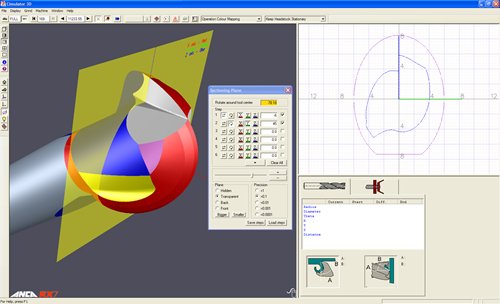
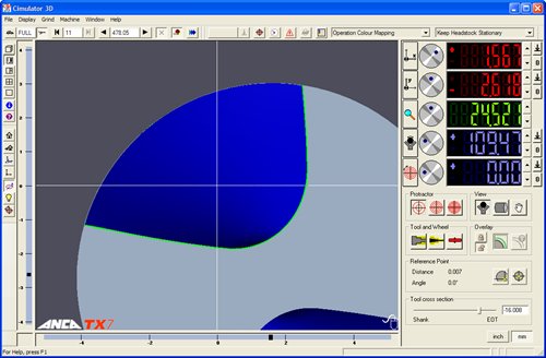
The enhanced sectioning plane in V7 allows precision placement via numerical rather than mouse control. This allows cross-sectional features to be precisely measured. In this example, the hook angle is being measured on a ball mill at a 45 degree orientation.
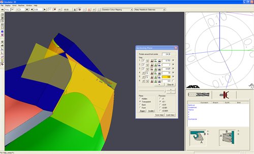
The ability to precisely position the cross-section plane now allows accurate measurement of various features. In the example pictured, the K-Land angle on a drill-point can be easily measured along the drill-point angle. This new ability makes Cim3D V7 unique among all other tool simulation packages.
In-Depth Cycle Time Estimation
Analysis of cycle time within the simulation environment allows optimisation of grinding moves to achieve the goal of maximising machine productivity by producing more tools per hour. Toolroom RN31 introduced an auto-approach move enhancement that automatically optimises all approach moves between operations so that cycle time saving can be automatically achieved by simply using Toolroom RN31. However, gap minimisation and feedrate optimization is an important step to achieve an efficient grinding process. Cycle time estimation within Cim3D has been extended in V7 by breaking down total cycle time into contact time, air time, gap time and rapid-move time. This allows improved analysis of the grinding process and the ability to better evaluate the effect of feedrate and gap-distance changes.
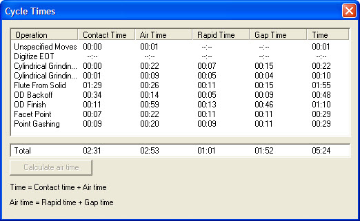
Cycle time estimation has been enhanced in V7 by breaking down total cycle time into various categories such contact, air, rapid and gap time. (Where rapid + gap time = air time). This allows improved analysis and optimisation of cycle time.
Smaller scale software enhancements affecting common tasks are often the ones most appreciated by regular users. An example of such an enhancement in V7 is the simplification of measuring between two points in the measurement view. The measurement view now features a way to set a reference point. As the tool is moved in the measurement view, the distance and angle from the set reference point is displayed on-screen. This is useful to precisely measure many geometric features such as land widths, radii, web thicknesses, etc.
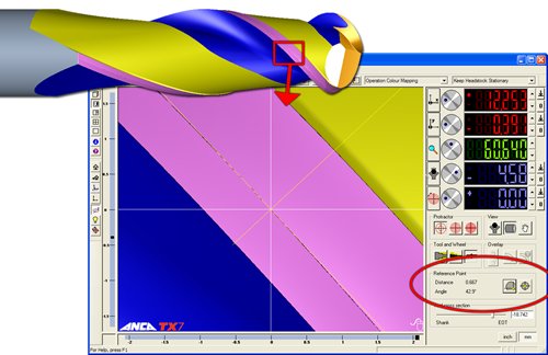
A simple enhancement for a commonly used task in V7 is measuring between two points within the measurement view. Selection of any reference point provides the ability to measure distances and angles easily.
New Machine and Tooling Models
Other enhancements in Cim3D include updates of mechanical models. ANCA’s new MX7 machine is now fully supported in V7 as well as related accessories such as the new MX7 P-Axis. This will allow collision detection for customers with MX7 machines. The Arobotech pad length for the P-Axis is now also adjustable via the machine configuration dialog for both TX7 and MX7 machines as well as the addition of the micro-adjustable pop-up steady and shoes. Tailstock models have been added for the RX7 and TapX machines.
The release of Cim3D V7 represents another milestone for this industry-leading software package by providing a range of productivity enhancements. Continual improvement of our software products ensures that our customers benefit from the competitive advantage of using ANCA solutions. We encourage our customers to provide feedback and improvement suggestions for consideration into future products. All feedback is reviewed and can be emailed to marketing@anca.com.
Contact your local ANCA representative today to order your copy of Cim3D V7.
15 June 2011