E-Sharp News
June 2012
The long anticipated release of ANCA’s latest instalment of the industry leading tool design software suite, ToolRoom 2012, will see ANCA customers benefit from a wide variety of new enhancements. Here we explore a few of the main features ToolRoom 2012 has to offer.
Endmills was one of the main focus areas for ToolRoom 2012. New features vary from major developments to minor enhancements combining to deliver a new ToolRoom software package that will greatly simplify the way endmills are programmed and ground on ANCA machines. The goal was to expand on the flexibility that our customers expect from ANCA software, yet simplify the process of programming production ready tools directly on the machine.
Simple but Flexible Programming with the new Endmill Wizard
The new End Mill Wizard (EMW) is one such feature that was developed to achieve this goal. The EMW guides the operator through a simple step-by-step process asking for simple tool specifications along the way. The wizard uses this input to automatically produce the grinding program using a set of predefined rules and calculations. Geometry, feedrates, and all other parameters are automatically calculated. The wizard will also automatically select appropriate grinding wheels from those already mounted in the machine or simulator. Where it cannot find an appropriate wheel, it will provide a recommendation. At the end of the process the operator can be confident that a good tool will be ground after pressing the “GRIND” button.

The new End Mill Wizard supports creation of new Square End, Corner Radius, Chamfer & Ballnose tools
The End Mill Wizard simplifies programming, reduces set-up times and eases the requirements for operator training. Although simple to use, the wizard is a powerful tool that is able to generate a vast range of endmill types typically produced within the industry.
What sets the wizard apart is a unique customisation option. Rather than be locked into the default wizard behaviour, the option exists to completely customise the wizard. An example of a common benefit of this flexibility is where tools are produced under different product ranges. For example, a manufacturer may produce a 'High Performance' range of endmills as well as a 'Standard Range'. The geometry and process used to produce these tools may be different and therefore customisation of the wizard is required.
The way a parameter is assigned or calculated from the wizard can be customised. This can be done for every single parameter in the software providing total flexibility. For example, a relief angle can be given a fixed value, calculated from a formula involving other dimensions such as tool diameter, or can be derived from a table of known values. Once customised, it is a simple matter of selecting the customised range from the first page of the wizard. Additionally, the customisation information is easily transferred to other machines or simulators.

In the above image High Performance and Standard Range have been customised
as a demonstration that the End Mill Wizard is completely customisable
Immediate Feedback with Free Integrated 3D Graphics
Once a tool is generated from the wizard, the operator can then take advantage of the integrated 3D graphics which is another major enhancement within ToolRoom 2012. A 3D model of the tool appears in the iGrind tool design software and is updated dynamically as parameters are changed. The 3D model takes only seconds to update, providing instant feedback for any geometry changes made.
Apart from reducing programming time on simulators, the 3D model is an important aid when programming tools directly on the machine. The operator is now able to inspect the 3D model on the machine before commencing the grinding operation. This increases confidence that the tool will be ground correctly and eliminates (in many cases) the need to verify geometry on a simulator PC. To help cater for this, the interface includes touch-screen friendly controls to allow manipulation of the 3D model at the machine's control panel.

Pictured is the dynamic & fully integrated 3D model capabilities of IGrind software in ToolRoom 2012.
The 3D model updates immediately as changes are made
The 3D model is available for all tool types within iGrind, not just end mills. The benefits of having the integrated 3D model extend well beyond just inspection. For example, the cycle time estimation is also dynamically updated as geometry and/or process parameters change. The cycle time for the entire tool, as well as the time per operation is shown. This instant feedback is particularly useful to reduce cycle times by optimising process parameters.
The 3D model can also be sliced at any position to inspect the 2D cross-section. As per the 3D model, the 2D cross-section may be colour coded by operation, wheel selection, or other available options. Simple measurements are possible to verify the programmed geometry. This type of measurement is typically best performed in the 2D view rather than the 3D view and therefore can greatly aid in verifying the programmed geometry.

This screen shows that in addition to a 3D view, the model can be sliced at any position
to inspect the cross section & perform basic measurements directly within iGrind
Dramatically Faster Simulation
The mechanism used to generate the integrated 3D model is fast and efficient and is now also used with ANCA’s CIMulator3D software. As a result, users of ToolRoom 2012 may experience significantly faster simulation times regardless of the CIMulator3D version currently used. Depending on the complexity of the tool, speed increases of up to 10 times could be achieved. Common tools such as taps and ballnose endmills also significantly benefit from this feature.

Listed are the significant improvements in simulation times for all
Cimulator 3D software users using ToolRoom 2012
Accurate Edge Preparation (K-Land) without Digitising
A significant leap forward is the ability for iGrind to analyse the 3D model within the design environment. This ability has greatly simplified tasks that were either not possible, or often difficult to achieve. One such example is K-Land grinding on drill points.
Up until ToolRoom 2012 it was necessary to digitise the cutting edge on the drill in order to determine the lip geometry. The K-Land is typically 50 microns in thickness, half the width of a human hair. Accurately digitising the drill geometry and grinding the K-Land to tolerance can consume the majority of the set-up time for such drills.
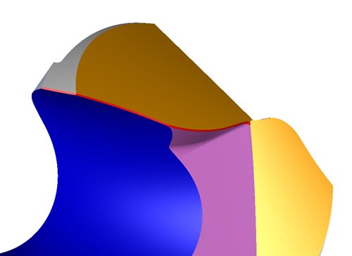
By analysing the 3D tool model, iGrind can now accurately determine the drill lip edge (as highlighted by the red line on the 3D model above), simulate & grind the K-Land. All without needing to digitise
iGrind can now intelligently analyse the 3D model and determine the drill cutting edge, eliminating the need to digitise during manufacturing. Assuming good machine set-up, only minor adjustments may be required to achieve the K-Land tolerance. Therefore set-up times for such tools are significantly reduced and the possibility of creating scrap tools reduced.
Complex Profiles Now Perfectly Calculated
The ability to analyse the 3D model has also been extended to profile tools to solve the long standing issue of flute hook face compensation. To grind an accurate profile onto a tool the software needs to calculate how to compensate for the curved surface of the flute face. When the flute shape is complex there was previously no alternative but to perform often lengthy digitising operations on the flute. This not only consumed set-up and cycle time but also meant that the geometry could not be easily simulated or verified prior to grinding.
With ToolRoom 2012, the Profile software is now able to calculate the compensation required to accurately produce a cutting edge on the tool regardless of the complexity of the flute shape or the profile. And the grinding process and geometry can be verified directly within CIMulator3D without requiring any digitising data. It is common for profile tools to be ground in very small batches. Therefore, the minimal set-up times and zero scrap rates offered by ToolRoom 2012 will boost your profitability and competitiveness in profile tool grinding.

Profile screen shot above shows how the required flute hook face compensation can
now be determined in ToolRoom 2012 using the 3D model, eliminating the need to digitise
Laser Digitised Profiles
ToolRoom 2012 also includes support for laser digitising and compensation of ballnose, corner radius and profile tools. Laser digitising is an optional accessory on ANCA machines. Tool geometry can be automatically and accurately measured and compensated in-process without the need to remove the tool from the machine.
ToolRoom 2012 includes support for laser probing and compensation of ballnose, corner radius & profile tools
Laser digitising and the automatic hook compensation feature in ToolRoom 2012 mean that profile tools can be easily programmed within iGrind, verified in CIMulator3D, ground on the machine, and automatically compensated with minimal effort and complication. As the tool does not need to be removed from the machine, the requirement for special work-holding or orientation software is eliminated. The machine remains productive throughout the entire process without the need for operator intervention and eliminates the issue of the machine cooling down while a lengthy external measurement process takes place. Laser probing can also eliminate the need for expensive measurement machines. As you can see, the advantages of Laser probing are numerous and significant.
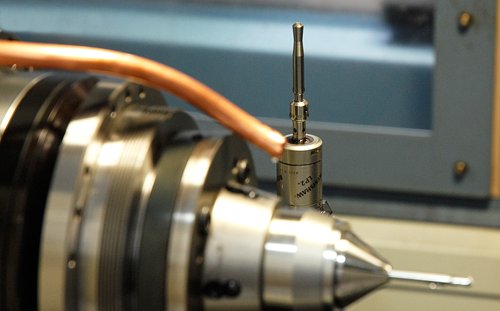
The optional Wheel Probe pictured is supported in ToolRoom 2012 & introduces a
new level of accuracy & repeatability into your grinding process
Wheel Qualification for Further Set-up Time Reduction
To further enhance automation and repeatability, the Wheel Probe feature can be fitted to free the operator of the task of qualifying wheels. The accuracy and repeatability of the probe has proven to be superior to the manual method of internally qualifying wheel packs. The manual method can result in large differences in qualified values from one operator to the next.
ToolRoom 2012 includes many other enhancements aimed at reducing set-up times, simplifying programming, increasing accuracy and repeatability, improving automation and producing new geometries not previously achievable.
This article has touched upon some of the main enhancements our customers will benefit from when upgrading to ToolRoom 2012, or when they purchase a new machine.
2 June 2012