E-Sharp News
September 2020
ANCA’s comprehensive software and hardware skiving cutter solution
Xiaoyu Wang, Product Manager – Gear Tools
ANCA CNC Machines
Skiving in demand
Industry forecasts and studies on the worldwide demand for gears projected a rise of 6% per annum through 2019, to $221 billion. Motor vehicle transmissions alone account for 45% of the entire gear market [3]. The electrification of vehicles is expected to have a major impact on the gear industry. In a conventional drive train, there are 25 to 30 gears. Instead of 9-10 levels of gears, electrical engines feature a simpler transmission with only a single or twin-speed being common.
High engine speeds of up to 20,000 rpm in electric vehicles (EV) means that the gear wheels in the transmission must meet tighter geometric tolerances. Internal gears in a planetary gear set are prevalent in the new drive train designs. To improve the accuracy as well as the efficiency in the manufacturing process, the gear industry is increasingly viewing skiving as the solution. Skiving is six-eight times more efficient than shaping, more flexible than broaching, and can produce both internal and external gears[4]. The rising popularity of skiving has caused a surge in demand for skiving cutters. But the industry is experiencing up to 20 weeks lead time, making skiving cutter supply the bottle neck for wide spread adoption of the technology.
Skiving cutter design
Detailed and complex geometrical calculations are fundamental to skiving cutter design. The foundation is the skiving kinematics, which is the basis for the difference between skiving cutters and conventional shaper cutters.
Skiving Kinematics
The initial skiving process was developed and patented in 1910 by Wilhelm von Pittler [2]. The kinematics of skiving combines the rolling motion and milling motion, requiring the cutter and the workpiece to be synchronised at high speed. From the 1960s through to the 90s, many attempts were carried out to build a skiving machine with the required synchronisation and rigidity. But only in the last 10-15 years have machines become available, which make skiving a practical solution.
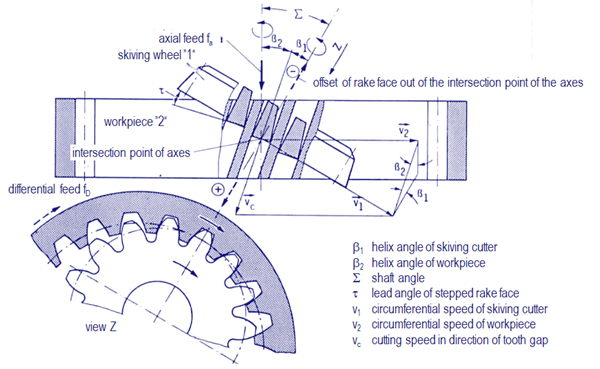
Figure 1. Skiving kinematics. Source: König, Fertigungsverfahren Band 1
Skiving cutter vs. shaper cutter
A skiving cutter is a generating pinion type gear cutter, which looks very similar to a conventional shaper cutter. Upon considering the relative movement between the gear (workpiece) and the cutter, it is clear that the principles of the shaper cutter are based on a pair of parallel axes gears. On the other hand, skiving cutters are based on a pair of gears with crossed axes. A pair of crossed axes gears only contact at a single point, and subsequently the profile and geometry of a skiving cutter are more complex than for a shaper cutter. In addition to the workpiece profile, the determination of a skiving cutter’s geometry requires the kinematics of the generating box: centre distance and rolling circles according to the gear ratio, the shaft angle, and the tilt angle.
Following the principles set out in DIN 1829 standard, the cutting edge of a skiving cutter can be viewed in terms of the enveloping gear, which corresponds to a virtual cylindrical gear. For skiving cutters, the profile of the enveloping gear does not represent an ideal involute as is the case for shaper cutters.
Accuracy requirement
Skiving cutters are classified as pinion type cutters, and currently there is no industry standard specific for them. The industry has widely adopted DIN 1829 – part 2 as the default measurement standard. DIN 1829 – part 2 stipulates the features to evaluate and the tolerance allowance to qualify each quality class. For example, for cutters with a reference diameter less than 50mm and module size less than 1mm, the required form error f
f need to be less than or equal to 2 microns to qualify as DIN AA.
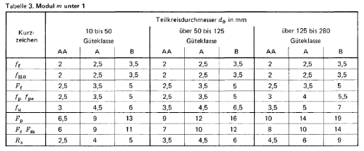
Figure 2. Measurement Standard table 3. Source: DIN 1829 – part 2
Due to the novelty of the skiving cutter, many industry benchmark measurement machines do not have inbuilt mathematical models for evaluating the cutter profile, posing a special challenge for the manufacturing and quality control process.
ANCA’s skiving solution
Responding to the market demand, ANCA developed a comprehensive software and hardware solution, to ensure the cutter is correctly designed and optimised in an efficient manner. First unveiled at EMO Hannover in 2019, the new GCX Linear sets the standard for skiving cutter manufacturing. With all-linear axes to drive accuracy, the GCX Linear can finish all operations in one setup. It comes with features specially designed for manufacturing skiving cutters and shaper cutters to the highest quality class DIN AA.
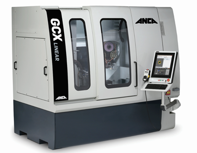
Figure 3. ANCA GCX Linear machine
Comprehensive software package
The GCX software package comprises multiple software components for manufacturing and resharpening pinion type gear cutters. It includes design, simulation, grinding sequence programming, wheel editing and wheel dressing, and support for full virtualisation of the manufacturing process, which reduces setup time and the chances of scrap.
Gear cutting tools like skiving cutters and shaper cutters have complex geometries. Essential to the design process is iterative optimisation. This is especially important under marginal workpiece conditions, such as interfering components and collision conditions. On the design station, the cutter can be designed from basic gear workpiece data. The skiving kinematics can be simulated to verify the cutter design and potential collisions rectified.
iGrind software supports both stepped and conical rake face, and comes with many other operations such as digitising, fluting, cylindrical grinding and separate tip relief grinding. The grinding process can be simulated in CIMulator3D and parameters can be analysed.
Accurate wheel dressing
Dressing the complex profile wheel is critical for achieving the high accuracy of the tooth profile form for skiving cutters. With the latest acoustic emission monitoring technology, AEMS adds an “ear” to the GCX Linear that is tuned in to the fine pitches of wheel dressing. AEMS learns as well as listens, as it is built with an advanced supervised machine learning algorithm. The system can be trained to pick up the right tunes for perfect dressing in a noisy production environment. It ensures the wheel profile is dressed within micron accuracy in the least possible time while minimising the reduction in grinding wheel size.
Improved thermal stability
To meet the stringent accuracy requirement, thermal stability of the machine is critical. ANCA developed Motor Temperature Control (MTC, patent pending) technology to actively manage and maintain the temperature of the motorised spindles in the GCX Linear machine. Apart from dramatically reduced machine warmup time, improving productivity and machine utilisation, most importantly, MTC maintains consistent thermal stability of the spindle over time regardless of changes in spindle load or speed, or spindle cooling coolant temperature. This greatly improves the dimensional stability of grinding results.
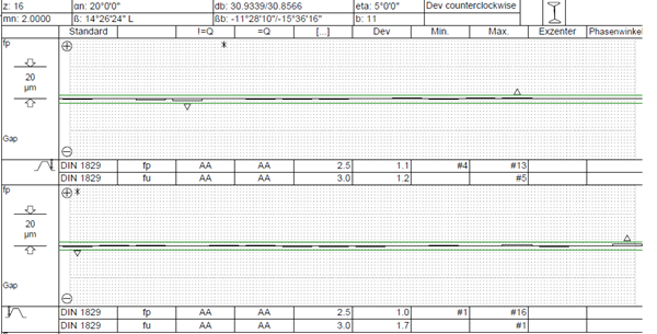
Figure 4. Example pitch measurement report of a skiving cutter produced on GCX Linear with individual pitch error fp measured around 1µm, adjacent pitch error fu measured less than 2µm.
References
- Wilfried König. (n.d.). Fertigungsverfahren Band 1. ISBN 978-3-662-07205-9 - 1997
- Pittler von, W. Verfahren zum Schneiden von Zahnrädern mittels eines zahnrad-artigen, an den Stirnflächen der Zähne mit Schneidkanten versehen-en Schneidwerkzeuges, Patent Application, Germany, March, 1910
.
- World Gears Industry study with Forecasts for 2019 & 2024 The Freedonia Group
- Dr. H.J. Stadtfeld Power Skiving of Cylindrical Gears on Different Machine Platforms, American Gear Manufacturers Association Fall Technical Meeting, 2013
19 August 2020