E-Sharp News
June 2022
Explore various ways of using the material removal rate Q to optimize the tool grinding process by improving cycle time and reducing the wheel wear
What is material removal rate, or Q?
MRR Material Removal Rate, usually denoted as Q, is an essential parameter for any subtraction manufacturing process. A higher MRR means more efficient operation and often reduced cycle time. In theory, the definition of MRR is quite simple - the volume of material removed during the manufacturing process divided by time gives a volume/second rate mm
3/s.
Q = dVr / dt
A complex cutting tool is exceptionally complicated, geometrically; the task of estimating the volume per cut quickly evolves into a challenging mathematical calculation that is impossible to perform in practice. Subsequently, the opportunity to optimise the grinding process through analysing the key process indicator MMR is often unexplored, until now…
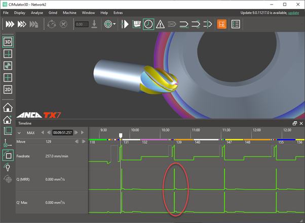
Q on a timeline
In the latest CIMulator3D software, the simulation engine will 'grind' material progressively, calculating the MRR by subtracting the volume of the remaining workpiece from a previous move time. The MRR over time displays as a timeline chart, which gives precise MRR over the entire grinding process. Simply dragging the timeline cursor to any specific point, the MRR at the time appears as a readout on the right of the control panel. Now that the math is done by the CIMulator3D, this article will demonstrate a few ways to use the MRR to improve production efficiency and reduce cost.
Improve wheel life and grinding efficiency
Grinding wheels perform best when used in the manufacturer's recommended MRR range. High MRR than Q
max causes rapid wheel breakdown while grinding on too low MRR; lower than Q
min can lead to wheel loading and wheels becoming dull. The wheel achieves the legendary self-sharpening state when grinding in the optimal range.
For deep cut operations such as heavy fluting, the number of passes should be divided according to the MRR. Ideally, the MRR of the grinding moves should be within the manufacturer's recommendation. Operations or passes exceeding the Q
max will overstress the wheel, and those below the minimum Q
min will dull the wheel.
The MRR in CIMulator3D provides a theoretical basis. In practice, there are many factors such as coolant setup, quality of the grinding wheel, and power of the grinding spindle, which impact the wheel's performance. An operator with experience using a particular wheel brand could use this graph to determine the division of passes to ensure optimum performance and productivity.
Determine the dressing frequency
The grinding wheel will inevitably wear over several tools or passes. ANCA's iGrind and Dresser software are well-integrated; for example, fluting operations have a built-in dressing panel, which assists the operator in pre-programming sticking or dressing after a certain number of tools or passes.
How often a wheel should be resharpened comes with experience; alternatively, the dressing frequency can also be obtained by designing experiments and building a practical database.
Plotting spindle power on the machine over the pre-calculated MRR from simulation, the graphs should correlate, as grinding off the same amount of material requires the same amount of energy.
If the spindle power departs from the theoretical MRR, it could indicate wheel problems. For example, if spindle power increases over time for the same expected MRR, it might suggest the wheel needs resharpening. This observation should be the basis for the operator to determine the dressing or sticking frequency. Before the deviation occurs, scheduled automatic sticking of the wheel will save cycle time and protect the grinding wheel.
Adjusting grinding feedrate
When simulating the grinding process, the user can easily spot MRR changes. A jump from zero to a value is when the wheel is about to touch the ground tool. Combining it with the feedrate chart, the user can increase the feedrate before the jump of MRR, effectively reducing cycle time.
On the other hand, an unexpected sharp shoot in MRR means a sudden overload of the wheel, which will cause real-world damage. Perhaps, rapid feedrate was accidentally used while approaching the workpiece. A quick check of the MRR chart, overshoots can be easily spotted and issues resolved in simulation.
Optimise adaptive grinding
Adaptive grinding adjusts the feedrate based on the target spindle load. Using this function appropriately helps reduce cycle time. However, one of the pitfalls of applying adaptive grinding without considering the MRR is: despite the wheel manufacturer's recommended maximum material removal rate Q
max. Adaptive grinding could potentially turn the feedrate so high the MRR exceeds the Q
max, resulting in rapid breakdown of the grinding wheel. The feedrate should be adjusted based on the MRR to protect the grinding wheel and maintain a stable process.
Specific volumetric removal rate Q'
The other helpful graph is the specific volumetric removal rate Q', defined as the material removal rate of the workpiece per unit width of wheel contact. The CIMulator3D engine uses the overall wheel width in contact with the tool at any given point in time to calculate the specific volumetric removal rate. Combining the specific volumetric removal rate and the wheel section colour mapping, the user can identify the wheel areas that carry most of the load and, therefore, require more frequent dressing or sticking.
14 June 2022